3D Pointcloud Groundfloor Segmentation for Intel® RealSense™ Camera and 3D LiDAR
This demo showcases an Intel® algorithm designed for the segmentation of depth sensor data, compatible with 3D LiDAR or a Intel® RealSense™ camera inputs. The application processes either a 3D pointcloud or a depth image, producing a refined 3D pointcloud as output. Each endpoint within this pointcloud is classified, distinguishing between ground floor, elevated surfaces, obstacles and structures above ground level.
The algorithm addresses situations like non-flat floors, ramps, inclines, declines, overhanging loads and other challenging conditions. Its capabilities extend beyond standard segmentation approaches, making it suited for diverse scenarios.
This tutorial guides users on running the algorithm from Robotics SDK using either a 3D LiDAR or a Intel® RealSense™
camera input, generating segmentation/labeled_points and segmentation/obstacle_points topic of type
sensor_msgs/PointCloud2. The first output topic assigns labels (ground, elevated, obstacle or above the roof)
to points within the sensor’s 3D pointcloud.
The second topic provides a reduced pointcloud containing only points labeled as obstacles.
Getting Started
Robotics SDK provides a ROS 2 Deb package for the application, supported by the following platform:
OS: Ubuntu 22.04 LTS
ROS version: humble
Install Deb package
Install ros-humble-pointcloud-groundfloor-segmentation Deb package from Intel® Robotics SDK APT repository
sudo apt update
sudo apt install ros-humble-pointcloud-groundfloor-segmentation
Run the Segmentation with Intel® RealSense™ Camera Input
Execute the following command to run the demo using a Intel® RealSense™ camera input, after starting the Intel® RealSense™ ROS 2 node.
source /opt/ros/humble/setup.bash
ros2 launch pointcloud_groundfloor_segmentation realsense_groundfloor_segmentation_launch.py
One can view the list of running ROS 2 topics by typing ros2 topic list in a terminal.
/camera/depth/camera_info
/camera/depth/image_rect_raw
/parameter_events
/rosout
/segmentation/labeled_points
/segmentation/obstacle_points
/tf
/tf_static
Note
Your topic list may differ, if you use additional ROS 2 nodes or other camera settings.
The ROS 2 launch file provides additional arguments, for example to run the ROS 2 node only together with a camera, or with rviz. These can be activated as follows:
- Terminal 1:
source /opt/ros/humble/setup.bash
ros2 launch realsense2_camera rs_launch.py enable_infra1:=true align_depth.enable:=true enable_sync:=true init_reset:=true pointcloud.enable:=true camera_namespace:=/
- Terminal 2:
source /opt/ros/humble/setup.bash
ros2 launch pointcloud_groundfloor_segmentation realsense_groundfloor_segmentation_launch.py with_rviz:=True standalone:=True
The commandline option ‘-s’ will show all available flags.
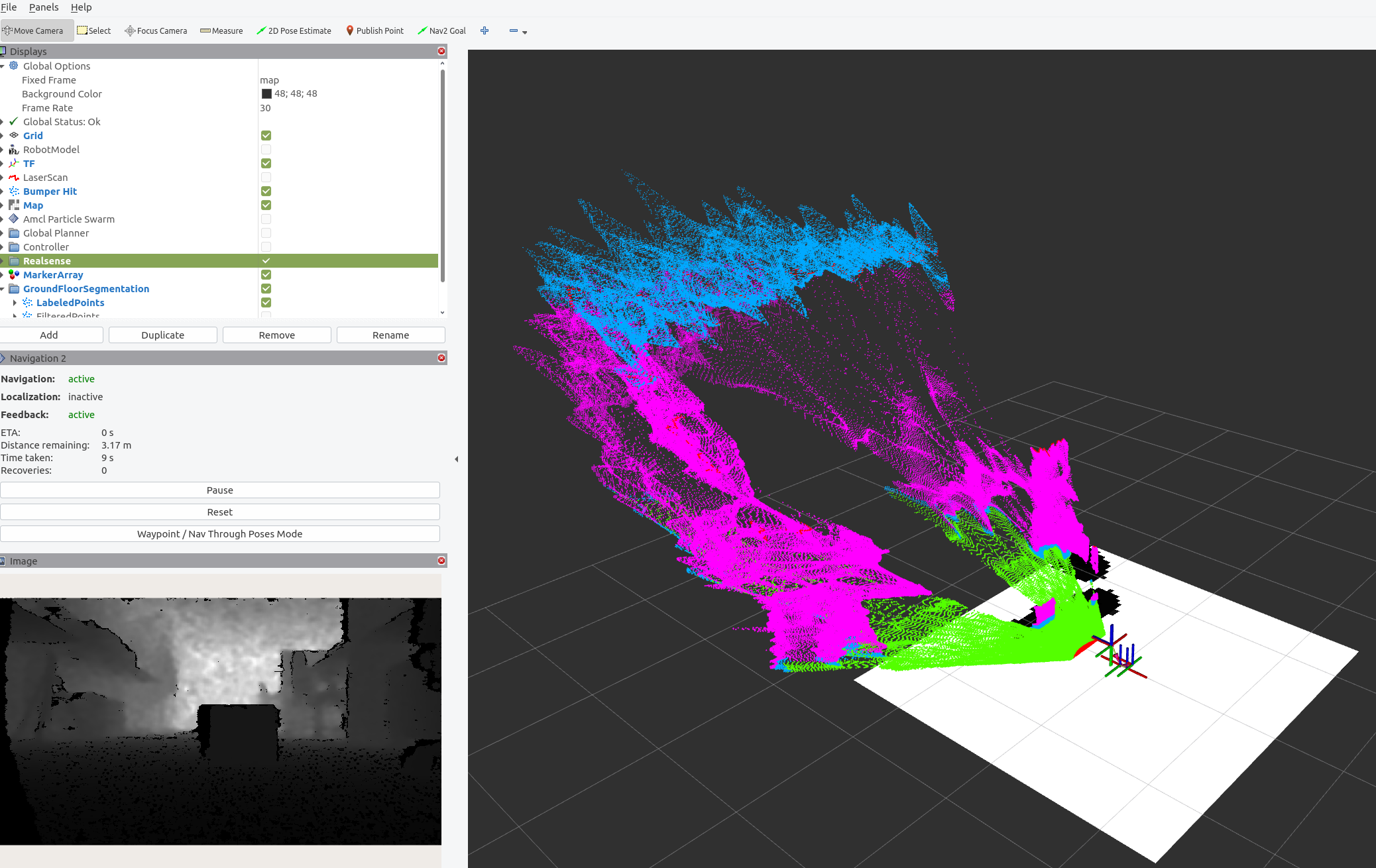
In case of the standalone execution, the rviz view for the labeled pointcloud should look as follows:
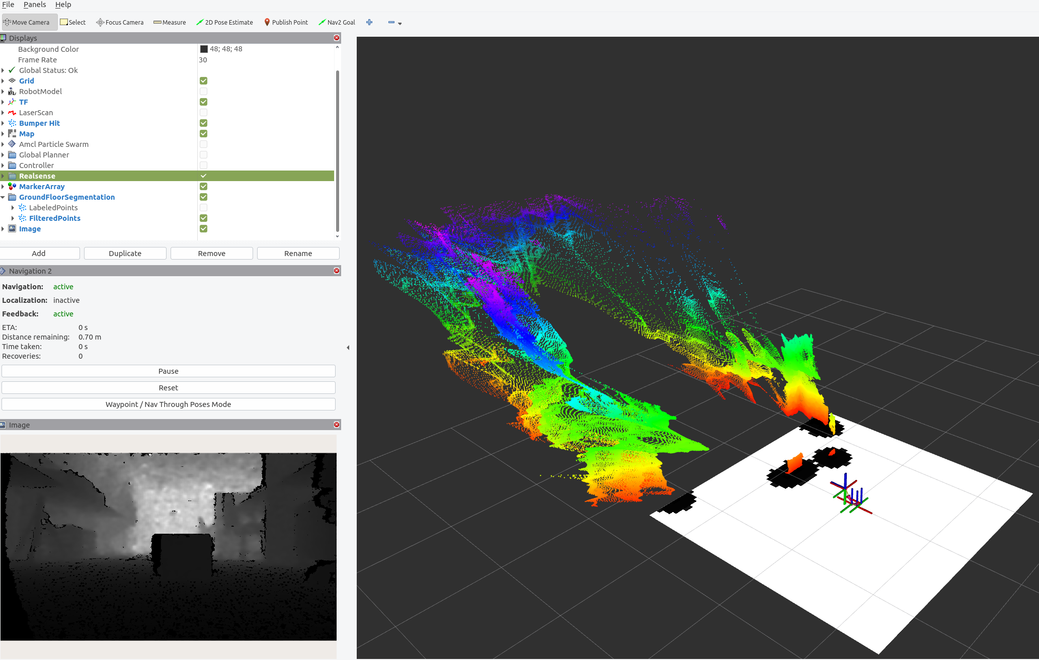
In case of the standalone execution, the rviz view for the filtered pointcloud should look as follows:
Run the Segmentation with a 3D LiDAR sensor
Execute the following script to run the demo if a given pointcloud, for example from a 3D LiDAR sensor should be segmented.
source /opt/ros/humble/setup.bash
ros2 launch pointcloud_groundfloor_segmentation pointcloud_groundfloor_segmentation_launch.py
One can view the list of running ROS 2 topics by typing ros2 topic list in a terminal.
/input/points
/parameter_events
/pseudo_camera/depth/camera_info
/pseudo_camera/depth/image_rect_raw
/rosout
/segmentation/labeled_points
/segmentation/obstacle_points
/tf
/tf_static
Note
Your topic list may differ, if you use additional ROS 2 nodes or other camera settings.
The LiDAR node, that needs to be started in parallel, has to provide the topic /input/points otherwise the topic has to be remapped.
Run the Segmentation Algorithm with the Teleop Application
This use case is intended for the teleop application running on the Aaeon robot, as described on page Robot Teleop Using a Keyboard. It leverages the similar functionality of the default teleop application. Therefore, please prepare the robot accordingly and start all required applications.
Afterwards open three terminal sessions:
- Terminal 1: Run the following commands to establish a TF link between robot and camera:
source /opt/ros/humble/setup.bash
ros2 run tf2_ros static_transform_publisher 0 0 0.1 0 0 0 1 /base_link /camera_link
- Terminal 2: Run the following commands to establish a TF link between robot and map:
source /opt/ros/humble/setup.bash
ros2 run tf2_ros static_transform_publisher 0 0 0 0 0 0 1 /map /odom
- Terminal 3: Run the segmentation application with Intel® RealSense™ camera input:
source /opt/ros/humble/setup.bash
ros2 launch pointcloud_groundfloor_segmentation realsense_groundfloor_segmentation_launch.py with_rviz:=True
Adjusting Application Parameters
The ROS 2 node supports a set of parameters, that can be found under:
/opt/ros/humble/share/pointcloud_groundfloor_segmentation/params/
There is one example configuration how the application’s output can be used for the ROS 2 nav2 application, and a second file providing parameter values for the segmentation task. These include:
base_frame:This is the ROS 2 TF frame that the underlying algorithm operates on. The default value is
base_link. There must be a complete transform between the sensor frame and thisbase_frame.
use_best_effort_qos:Defines if
best_effortQoS should be used. By defaultreliableis used.
sensor.name:Name of the connected sensor e.g. camera or realsense_camera. The default is
camera. This is the prefix of the input topic, e.g. /camera/depth/image_rect_raw.
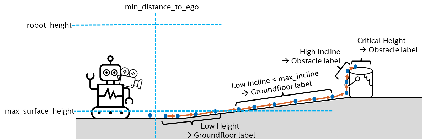
sensor.max_surface_height:The maximum height of a perfectly flat groundfloor. Default value is 0.05 meter. If no incline is detected, measurements higher than this value will be flagged as
obstacle.
sensor.min_distance_to_ego:Sensor measurements closer than this value are ignored during processing. Default value is 0.4 meter.
sensor.max_incline:The maximum allowed incline (or decline) of a ramp on the groundfloor. If an incline above this value is detected, the corresponding points will no longer receive the label
groundfloor. The default value is 15 degrees.
sensor.robot_height:Measurements above this value do not impose a collision risk for the robot and will be flagged as
above. The default value is 2.0 meter.
An example illustrating these parameters is provided in the image below:
Requirements
To achieve optimal output quality, it is essential to fulfill following requirements:
The input sensor should be forward facing, ideally in parallel to the groundfloor.
The ROS 2 TF tree between
base_frameand the sensor frame must be complete.Satisfactory input data quality is crucial. Incomplete depth images or pointclouds may result in incorrect labels.
Troubleshooting
Failed to install Deb package: Please make sure to run
sudo apt updatebefore installing the necessary Deb packages.You can stop the demo anytime by pressing
ctrl-C.For general robot issues, go to: Troubleshooting for Robotics SDK Tutorials .
The quality of the segmentation and labeling depends on the quality of the input data. Noisy data, especially major outliers could result in wrong labels. If this is the case, the input data should be pre-processed to reduce noise.