Create Your Own Robot Kit
This tutorial guides guides you through creating an autonomous mobile robot capable of exploring and mapping an area. It involves adding an Intel® compute system, placing a Intel® RealSense™ camera on top of any robot base, and using the Intel® Robotics SDK software.
Use the Robot Teleop Using a Keyboard ROS 2 node to validate that the robot kit’s hardware setup has been done correctly.
Requirements
Hardware Requirements
The robot base should contain:
Intel® compute system with Intel® Robotics SDK installed
Intel® RealSense™ camera
Robot base support (chassis) for the Intel® compute system and the Intel® RealSense™ camera
Wheels
Motor
Motor controller
Batteries for all components
Software Requirements
The robot base should feature a ROS 2 node with the ability to:
Publish information from the motor controller firmware into ROS 2 topics like wheel odometry.
Receive information from other ROS 2 nodes and transmit this data to the motor controller firmware. For example, it should be capable of receiving movement commands from ROS 2 Navigation 2 stack on the cmd_vel topic.
Provide robot specific information like the tf tree data with correct tf transformations. For example,
odomandbase_linkand their transformations.When using multiple robots, the ability to change these names for each robot like
robot1_odomandrobot1_base_link(more information can be found here).
Note
This ROS 2 node runs on the compute system and retrieving information from the motor robot’s controller via a wired connection, usually a USB connection.
Steps To Create Your Own Robot Kit
Step 1: Prerequisites
To create a functional autonomous mobile robot, follow the instructions of the manufacturer.
The standard assembly involves the following steps:
Mount the motors onto the lower chassis board and then assemble the wheels.
Fix the motor controller on the chassis board and establish connections with the motors.
Attach the Intel® RealSense™ camera and the SSD drive to the upper chassis board.
Mount the Intel® compute system to the the upper chassis board.
Connect the two chassis boards.
Establish a connection between the Intel® compute system and both Intel® RealSense™ camera and motor controller via USB.
Connect both the the Intel® compute system and the motor controller to a power source.
Power the Intel® compute system using a power source.
Turn on the power switch of motor controller.
Step 2: Integration into Intel® Robotics SDK
Start the robot base ROS 2 node on the native system OS or inside a Docker* container. To ensure proper functionality, ensure that both the robot base node and the rest of the Intel® Robotics SDK pipeline are configured with the same ROS_DOMAIN_ID.
Step 3: Robot Base Node ROS 2 Node
Introduction to Robotic Base Node
The Intel® Robotics SDK pipeline assumes that the robot base ROS 2 node:
Publishes
odomandbase_linkodomis used by the Navigation 2 package and others to get information from sensors, especially the wheel encoders. For more information refer to Navigation 2 tutorial on Odometry.base_linkrepresents the center of the robot to which all other links are connected.
Creates the transform between
odomandbase_linkIs subscribed to
cmd_velwhich is used by the Navigation 2 package to give instructions to the robot like spin in place or move forward
The Intel® Robotics SDK provides the following examples with the ros-humble-aaeon-ros2-amr-interface Deb package:
/opt/ros/humble/share/ros2_amr_interface/params/aaeon_node_params_uncalibrated_imu.yaml
/opt/ros/humble/share/ros2_amr_interface/params/aaeon_node_params.yaml
These samples are for the AAEON UP Xtreme* i11 Robotic Development Kit.
Robotic Base Node Deep Dive
This section details the commands required to startup the motor controller of an AAEON UP Xtreme* i11 Robotic Development Kit.
To start the node on the AAEON UP Xtreme* i11 Robotic Development Kit, you can reference and initiate it as follows:
Ensure that the
ros-humble-aaeon-ros2-amr-interfaceDeb package is installed.sudo apt update sudo apt install ros-humble-aaeon-ros2-amr-interface

Check the device name of the motor controller.
sudo dmesg | grep ttyUSB
The output should contain the
ch341-uartdevice providing the interface to the motor controller board.[1452443.462213] usb 1-9: ch341-uart converter now attached to ttyUSB0 [1452444.061111] ch341-uart ttyUSB0: ch341-uart converter now disconnected from ttyUSB0
Ensure the AAEON UP Xtreme* i11 Robotic Development Kit node configuration file has the proper USB device configured as value of
port_name.vi /opt/ros/humble/share/ros2_amr_interface/params/aaeon_node_params.yaml
Start the motor control node.
AAEON_NODE_CONFIG_FILE=/opt/ros/humble/share/ros2_amr_interface/params/aaeon_node_params.yaml

# Launch the AAEON Robot Motor Board Interface
ros2 run ros2_amr_interface amr_interface_node --ros-args \
   --params-file $AAEON_NODE_CONFIG_FILE \
   --remap /amr/cmd_vel:=/cmd_vel \
   --remap /amr/battery:=/sensors/battery_state
You can check the following:
ROS 2 topics
ros2 topic list
# The result for UP Xtreme i11 Robotic Kit is similar to:
# /amr/cmd_vel
# /amr/imu/raw
# /amr/initial_pose
# /amr/odometry
# /parameter_events
# /rosout
# /sensors/battery_state
# /tf
# The result for the Pengo robot contains multiple topics but the crucial to this pipeline are:
# /cmd_vel
# /joint_states
# /rosout
# /odom
# /parameter_events
# /tf
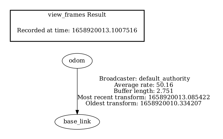
odomandbase_linkframesros2 run tf2_tools view_frames.py cp frames.pdf /home/<user> # Open the pdf through file explorer, it should look similar to:
Step 5: Navigation Full Stack
Create a Parameter File for Your Robotic Kit
The Wandering Application with Intel® RealSense™ Camera and Rtabmap Application in Aaeon Robot tutorial provides a parameter file for the AAEON UP Xtreme* i11 Robotic Development Kit, that file can be used as a template to create a parameter file for your robotic kit.
First install the tutorial.
sudo apt update
sudo apt install ros-humble-wandering-aaeon-tutorial
Use the AAEON UP Xtreme* i11 Robotic Development Kit navigation parameter file as a template, make a copy of it, and adapt the content to match your robot.
# Replace <your_robot>_robot_nav to a name that makes sense to your robotic kit.
cp /opt/ros/humble/share/wandering_aaeon_tutorial/params/aaeon_nav.param.yaml /opt/ros/humble/share/wandering_aaeon_tutorial/params/<your_robot>_nav.param.yaml
Make all of the changes that are specific to your robotic kit:
vi /opt/ros/humble/share/wandering_aaeon_tutorial/params/<your_robot>_nav.param.yaml
Replace the
aaeon-amr-interfacetarget with the generic robot node you created in “Step 3: Robot Base Node ROS 2 Node”.In the ROS 2 command file, change the Navigation 2 target so that
params_filetargets the parameter file you created in “Step 4: Robot Base Node ROS 2 Navigation Parameter File”.from:
params_file:=/opt/ros/humble/share/ros2_amr_interface/params/<your_robot>_node_params.yamlto:
params_file:=/opt/ros/humble/share/wandering_aaeon_tutorial/params/<your_robot>_nav.param.yamlIn the
ros-base-camera-tftarget, change the transform values fromstatic_transform_publisher. The values for x, y, and z depend on where your Intel® RealSense™ camera is set.
Start Mapping an Area with Your Robot
Place the robot in an area with multiple objects around it.
Check that Robotics SDK environment is set:
Run the following script to create a map by using the Wandering Application with Intel® RealSense™ Camera and Rtabmap Application in Aaeon Robot.
source /opt/ros/humble/setup.bash
export ROS_DOMAIN_ID=<value>
/opt/ros/humble/share/wandering_aaeon_tutorial/scripts/wandering_aaeon.sh
Follow the Wandering Application with Intel® RealSense™ Camera and Rtabmap Application in Aaeon Robot tutorial.
Troubleshooting
You can stop the demo anytime by pressing ctrl-C.
For general robot issues, go to: Troubleshooting for Robot Tutorials .